Back to Contents
Back to Tips and Tricks
Link to Sitemap
Kadee couplers on European HO stock
Kadee couplers are wonderful. They give a lovely hands-off style of operation and are very reliable. Both Dave and Steph use Kadees on their American and European models. In fact Kadee now produce a range of couplers #17 - #20 which fit the standard NEM coupler box. These couplers use the standard #5 coupler head but come with the head mounted on the standard NEM 'fish tail' by a double joint.
And the double joint is why Kadees work and other manufacturer's knuckle couplers don't. The head is allowed to move sideways and rotate in response to the uncoupling magnet; just as the standard #5 coupler does when used on American stock.
There are a couple of tricks we've found when using Kadees. The first and most obvious is to make sure you buy and use the Kadee coupling jig. The 'trip pin pliers' are also a very worthwhile purchase. Then we're into the few odd things we've found out as we've gone along:
Kadees were originally developed for use with American stock, which means no buffers and no swinging coupler pockets. So it is worth fixing the coupler boxes in place down the centre line of the chassis even if you're using the NEM fit couplers. We align the back 'palm' of the coupler with the buffer heads to give reliable operation that's free of buffer-locking. That usually means using a #18 coupler in vehicles with NEM boxes and close coupling guides.
And here we come to a slight difference of opinion. Steph has found the #41 (underset/long) coupler useful in a number of vehicles that don't have NEM coupler pockets. Dave has decided to standardise on the #17 - #20 family; fitting them directly to many models. Incidentally we both use close couplings within rakes of stock; nothing looks sillier than a rake of coaches with a scale half-meter between the corridor connections.
On the rest of this page we're showing a selection of models and their coupler fittings in the hope that they provide some ideas if you're having trouble fitting Kadees to any stock...
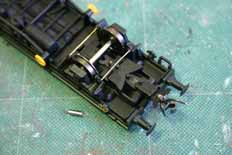
Pretty much the normal application this. On the Electrotren Transfesa van we fitted #18 couplers in the NEM pockets. The close coupling guides were then locked with brass wire - it can be seen in this picture passing through the coupling mechanism just in front of the axle.
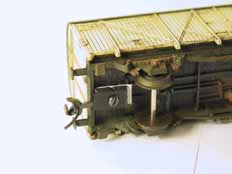
A #41 coupler is shown here on an elderly Roco van. One useful trick with this coupler unit is that the main fixing screw on this vintage of Roco vehicle can be used to secure the coupling box. Steph's ÖBB 2067 also uses #41s; their location was designed-in as the chassis was built.
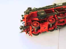
Unfortunately there are rarely clearances around the front bufferbeam on a steam loco to fit anything like a full Kadee coupling box. The alternative is to fit something like this; a #18 located on two pins. The home-brewed BR38.2 has simply had a U-shaped piece of brass wire soldered up behind the bufferbeam. Then a hole is drilled in the body of the coupler to take the front wire and the rear brass wire goes in the vee of the 'fishtail'. Okay - I know that doesn't make much sense, but the picture should help explain...
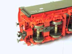
Instead of locking the NEM box in place in the chassis of your vehicle - why not make up a new, rigid, box? This is exactly what's been done here. Again the coupler is a #18; the 'box was built into the model of the auxiliary tender as the front of the frames were detailed.
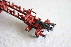
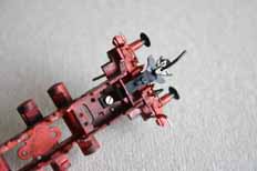
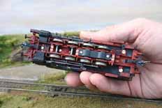
Occasionally (mainly with kit-built stock) there's the possibility of using a convenient screw to mount the coupling. On Dave's Weinert BR81 he's made up a couple of brackets from some brass strip, pinned the couplers to one end of each strip and drilled the other end to make use of screws already designed in to the kit's chassis.
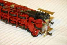
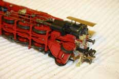
This was an experiment to try and give better appearance around the front of a loco. The Kadee #18 is effectively mounted on the scale front coupling. The hooks come from Alan Gibson and need reducing slightly to clear the Kadee coupler head. A hoop of wire is then soldered into the hook and the ends drop down and fit into holes drilled into the Kadee coupler. The back of the coupler is supported by a further two wires fixed into the chassis. There's half an idea here - although it worked on this detailed Roco BR50 I don't think it's going to be used on every loco we build as it's quite fiddly to do. Though there might have some benefits using the same principles in vehicles with continuous or deep bufferbeams, or locos with snowploughs, for example.
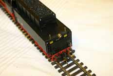
A back view of the BR50 mentioned above. The coupler is, again, a #18 and is fitted into the existing coupler box in the tender chassis. Like all other vehicles which use Kadees in NEM boxes, this one is locked. The coupler was fitted, then a hole was drilled through the chassis keeper plate, through the coupler box and into the coupling. Brass wire was then passed through the hole and secured with a drop of superglue.
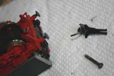
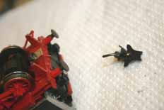
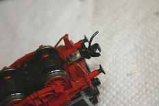
This is the one we keep getting asked about - early Roco tender locos. Most of the earlier Roco tender drives have this coupling fitting, certainly the BR01, 41, 44 and 58 all share the method with this BR17. Fitting a Kadee uses a variation of that used on our hand-built stock. The first pic shows the fitting on the tender before starting work; together with the #20 coupler. The mounting tab shown in the second photo uses a 4mm wide strip of 20/1000" (0.5mm) thick brass or nickel-silver. This is drilled 2mm dia. for the screw and two 0.5mm holes are drilled for wires to fix the coupler. As you can see the coupler itself has been cropped off to length. It can then be held in place and the 0.5mm holes spotted through. On the right-hand side you can see the assembled and fitted coupler. A length of wire has been soldered through the holes and acts as a set of pins to align the coupler, which has been superglued in place. One good thing with this method is that there's no modification required to any of the Roco parts and the coupler ends up at the correct height...
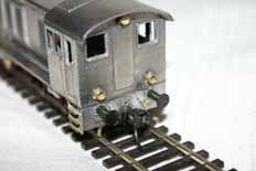
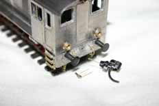
This method is useful if you've got to model a vehicle with a full depth bufferbeam - in this case my Weinert V36 (BR103). The method applies equally well to locos like Köfs; any model of which can be a bit of a pain to fit a Kadee to. It's a variation of that employed on the BR50, above; although this is much simpler to achieve. The coupling hook is Alan Gibson with a loop of wire soldered into it, this passes through holes drilled in the coupler body. A further piece of wire sticks out the back of the trimmed #18 coupler into the bufferbeam.


