Back to Contents
Back to Railways Page
Link to Sitemap
BR103
103 022-0
Believe me; you're not the first person to ask 'why a V36?'.
Well they're characterful locos, of a useful size for a layout and there are a couple of good models available. Lima's one looks good and runs well and the Weinert is, well, of a typically high standard. Interestingly Weinert consider the V36 one of their beginners kits and having seen how well their more advanced kits go together I was intruiged by the possibilties. Lenz now also do a model of a V36, but this is the DB's post-war build. So even though it's a good model, for me it was a non-starter. Guess which one I used. ;-)
To be honest I also thought it would be interesting to view it as a beginners kit and offer a review and some encouragement for the tyro model loco builder. After all it's available from Weinert in a variety of guises, DRG, DB and DR. Worth remembering too that examples ran in (many) other European countries, Austria, France, Belgium, Czechoslovakia (as it was then - before someone picks me up on it!) and Italy are all examples I know of. It would also be fun to see what, if any, compromises have been made so that it's easy to build and what an experienced modeller might make of it as a starting point.
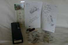
Promising start isn't it? This is, of course, for a model of a DR Era IV version, so I used kit 4235 which comes with RP25 wheels and a Faulhaber motor. All the usual Weinert gubbins are included; whitemetal castings for the non-functional parts, a bundle of lost-wax brass detail castings and an assortment of screws and other bits and pieces. As expected there's some good, clear instructions, also a nice set of decals (including the standard decal set which provides an ÖBB option as well as the expected DRG, DB and DR inscriptions) and etched plates for finishing. Standard European hook and loop couplings (not NEM coupler boxes though) are provided and there's even a crew figure. The major difference between this loco and any other Weinert kit I've seen before is the assembled chassis. In this photo it's had the coupling rods and motor cradle removed so that I can blacken the wheels and coupling rods. This is normally the first job I do after un-bundling any kit.
Parts required to complete vary upon the individual and any particular preference for running number. There are a couple of minor detail differences between locos on the DR. Three types of guard iron, two radiator styles and some (most?) locos had reconditioned cabs with larger side windows. I managed to find pictures of a couple of the locos offered by Weinert; V36 027 (as preserved) has the reconditioned cab and tram-style guard irons; 103 015-4 (in a 1979 dated picture) has the original cab and simple guard irons; 103 022-0 (in 1978) has a reconditioned cab and Einheits guard irons. Weinert supply an original cab and tram type guard irons. So I had a bit of modifying to do and needed a set of Einheitslok guard irons; Weinert spare part number 8550, for my model of '022. The simple guard irons are part 8554 and the early style radiator is now available from Gaßner, part V291...
In addition to any special details required you'll also need paints and something to stick it together. I used 70° solder for the whitemetal and 145° for the brass. But it struck me very early on that this kit is designed for assembly with adhesives. I also wanted to use Kadee couplers and would need a very good, small, DCC decoder. I know there's not much detail in this bit - I'll touch on these things as I go through the build. 'Cos I won't know the details until later on!
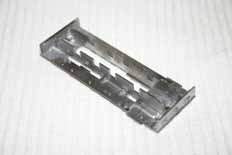
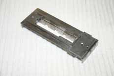
I started by cleaning up the running plates, chassis side plates and bufferbeams. Needle files were used to remove part lines and the parts were polished with a brass-bristle brush to clean back to a good surface for soldering. This polishing is also worth doing if gluing. I dropped the front footplate part on the chassis (sans motor) and trimmed some more material out around the pickups just to be on the safe side. The top of the right hand chassis side needs trimming flat, but it's simple to do and detailed in the text part of the instructions. The bufferbeams are helpfully marked on their backs; 'V', (vorder) for the front and 'H', (hinten) for the back one. The chassis sides are similarly marked with an 'L' and 'R'. As ever it's worth taking some time and care to ensure proper fit and finish. This assembly is pretty core to the construction of the kit so the running plate needs to be flat and the bufferbeams square in all dimensions.
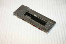
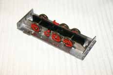
After this assembly stage the chassis was trial fitted once more to ensure the required clearances are there; particularly any that might result in a short circuit. The backs of the centre pair of wheels were just rubbing on the whitemetal chassis sides so a couple of gentle tweaks straightened that out.
The next job was to fit the details. So the holes were drilled as required by the drilling diagram and the castings were cleaned up. If you're fitting one of the alternative types of guard iron the pilot holes in the ribs on the back of the bufferbeam will need drilling 1mm diameter to take them. I use a Dremel minidrill with a steel-bristle brush in it to get the lost-wax castings to a nice shine. It helps the glue (or solder) to stick if they're nice and clean. A quick word on soldering brass to whitemetal: If you want to join brass and whitemetal with 70° solder the brass parts will need tinning with a conventional solder (I use 145°). 70° solder is formulated to attach to lead-based alloys so won't adhere properly to brass - but it does catch nicely to lead-based solders.
Some care is required when fitting the brake blocks to the left hand side of the chassis - the chassis must drop in and out cleanly and the wheels shouldn't (quite) touch the brakeblocks. Note that the rest of the brakegear hasn't been fitted yet - in fact it won't be until somewhere near final assembly. It appears that this is the point of our first detail modification as well. The more eagle-eyed will have realised that the small section of widened footplate around the front of the cab has been trimmed off - this feature only applies to certain DB locos...
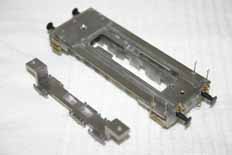
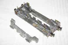
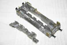
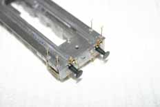
Getting to this stage took me a further couple of evenings. In part because I realised that the front lamps of the DR versions should have small brackets, rather than sitting on the front of the footplate. So they needed making up. A strip of brass the width of the lamp was fitted to the bottom with 188° solder so that they wouldn't come apart when soldered to the footplate. The front of the footplate is trimmed back so that the front overhang is the same as that at the rear. On the rear bufferbeam the extra holes for the platforms are filled in with solder; the vast majority of post-war locos (DB and DR) had them removed when the front/rear doors of the cab were sealed. I also removed the unused 'features' under the running plates; they're there for the Sifa gear of the late DB version. The buffers are glued in with thick superglue - everything else is soldered in one way or another...
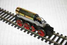
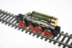
With the wheels and coupling rods blackened, and the latter's fluting painted red the chassis is re-assembled for a test run to make sure I haven't disturbed anything. I hadn't; it runs superbly. Other than the blackening and painting just mentioned this is how the chassis arrives, completely assembled and ready to run. The cradle with the motor needs seperating from the frame (with the wheels) in order to build the kit; just a case of carefully undoing the two screws from underneath. When it comes to re-assembly note that the shorter of the two screws is the one under the flywheel, also make sure that any shims that were built-in when it arrived are replaced.
Now the two visible screws on the underside of the chassis can be undone to seperate the motor cradle from the chassis proper. Gather the parts together and head for the next page. Ready? 1, 2, 3; Jump...!


