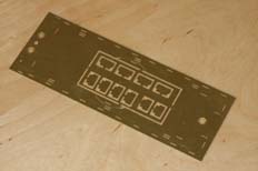
The size of the speaker is largely dictated by the width across the inside of the cosmetic frames. The largest ESU speaker that would fit is 40mm dia. So out with the dividers to find a centre and mark out the circle.
Here's a quick link back to the chassis assembly.
With the chassis progressing nicely, now seemed a good point to start construction of the tender body shell. This loco will be fitted with DCC and sound, so the first thing I feel I should mention is that in order to get the best sonic performance I could it was clear that the tender tank would be a good place to use as a resonance chamber for a suitably-sized speaker. That means that the tender tank has to be sealed and a mounting made up for the largest speaker that would fit.

The size of the speaker is largely dictated by the width across the inside of the cosmetic frames. The largest ESU speaker that would fit is 40mm dia. So out with the dividers to find a centre and mark out the circle.
You'll note that the circle is marked out with its centre in line with the slots for the middle tank top support (part 34). This is simply to avoid having any complications when it comes to cutting out the circle.
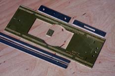
Here's the set of parts for the first round of assembly. Included in the picture are the rear bufferbeam and front drag box at the top, the tender tank platform with the rear coupling pocket in the centre and the valence strips towards the bottom. As you can see, on the L-class tenders the valence is shallower than on the E or E1. It's actually only 6" deep, hence the trimming, which was done while the parts were still supported by part of the fret as it makes the parts easier to hold and less fragile whilst sawing through (yes; with a piercing saw!). The width of the strip cut off needs to make allowance for the guide groove in the platform so needs making a scale 6", plus a half thickness of the platform which comes out at a total of 3.75mm. And it's worth being that careful, otherwise it won't quite line up with the loco, that also needs a 6" valence and won't have any guide slots...
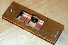
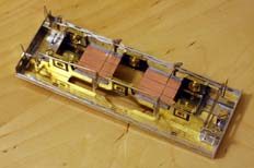
After soldering up the prepared parts I made sure of the fit to the chassis and also fitted the nuts to hold the body and chassis together. The front bolts need cropping off to fit under the tender-front footplate, I did this in-situ using a piercing saw, the running a file over the top. The screws will then de-burr when they're removed. Just be aware that both these photos show the tender chassis in it's earlier, incorrect guise... Yes, I am still feeling a mite sheepish about it!
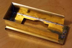
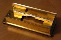
The main part of the tender tank is made exactly as described in the instructions. Unfortunately I had a couple of problems forming the flare, the main one of which was down to me not having built an SECR tender before and so forming it, LSWR-style, by folding. I realised I'd got it wrong when I tried fitting the corners. Whoops! After re-forming I don't think it's actually all that bad, the outside of the curve (tender top) is fine after some polishing out of odd tool marks. The inside of the curve (tender side) will need the application of some filler later on to make it nice and smooth.
Anyway, minor disasters aside, this is fairly straightforward. You can see that I also built-up the thickness of the speaker mounting hole with 1mm copper wire. Forming a 40mm dia. ring and then soldering it in one piece is the easiest way to do it, the excess can be trimmed off afterwards.
The next job is to run solder into the mounting slots that aren't going to be used in the platform. This is all part of the process of sealing the tender tank so it can successfully load the back of the speaker.
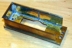
As I've already mentioned, I wasn't going to use the tank top supports (part 34) as they'd make it too difficult to seal the inside of the tank with solder. The middle one would also need trimming for the changes to the coal space required for an L. Instead, I cut off 4 lengths of 0.9mm brass wire to the same height as the spacers, these were soldered vertically to the inside of the tank sides, two near the rear corners and two about halfway down each side.
There are parts from the kit that can be used to help with the construction from this point, but most of it is going to require scratchbuilding - the coal space is a very different shape and the tender front requires changing for different toolboxes and shovelling plate.
So while I considered how I'd build the rest of the tender body, I moved on to preparing the wheels with their split axles.