Back to Contents
Back to Railways Page
Link to Sitemap
If you're not quite finished with the previous page, you can jump back here...
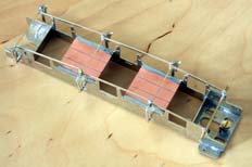
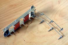
The brake shoes can go on now. Solder them to the cross rods only (i.e. not the hangers!), then trim the hangers to the face of the brake shoes. Don't solder on to the 1.6mm dia brake cross beam, but now is a good time to do a quick trial; if you're really lucky, the brake parts can then be unclipped from the hangers and the assembly will then un-hinge from the chassis to allow you to do the rest of the work. The main reason for me adopting this approach is to allow all the soldering to be completed before the hornguides are fitted and so they never risk coming to any harm from heat. As a further advantage the separate brakegear also makes life easier when it comes to fitting the wheels, painting, etc...
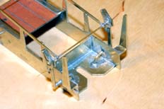
And now more twiddly bits - the guard irons were initially and incorrectly fitted as shown here You'll note that a right-angle bend towards the top of the guard irons gets them straight, vertical and in the right place. With a decent blob of solder in there they're adequately strong enough too. Perfect for a C, D, E, D1 and E1; just not correct for an 'L' where they're fixed to the outside frames and have a noticeable joggle in them. This was one of the things that required correction!
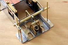
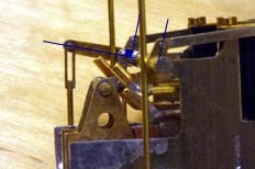
It's then a case of making and fitting the remaining parts on to the 1.6mm crossrod. There is a set of three tube sections required to make the ends of the cross rod and support the handbrake lever. With care (and a light oiling of the cranks on the pull rods) the tube sections and handbrake lever can be soldered in place and the brake pull rods will still rotate if the brake shoes are unclipped from the frames. You'll also no doubt have noticed that the sandpipes have made an appearance - 0.9mm wire soldered into the holes provided in the front spacer.
I was, fairly obviously, aiming for the best appearance with the brakegear. One thing I got from the General Arrangement drawing was the alignment of the pullrod cranks, being perpendicular to the small crank and handbrake crank. The picture with the cunning blue lines on it should help show what I mean. In order to get this correct I found out that the length of the lift links was pretty critical. It took me a couple of goes to get it correct.
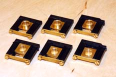
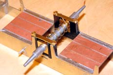
The hornblocks are the next job. The first photo shows them assembled ready for installation. Note that although all the screw holes in the plastic hornguide have been tapped, the top screws used to level the chassis haven't been fitted. The brass hornblocks haven't had the top spring plates fitted yet - though you could do. I'm also starting to look at whether some form of spring cup might be a better and easier solution. The guides themselves may need adjusting during assembly to get the hornblocks moving sweetly, gently opening the spacing in the slides as the keeper screws are tightened does the trick. I test the hornblocks by giving each one a little shake - you should hear the hornblock move freely with a little click as it reaches each end of its travel.
Fitting the hornblocks requires the front ones to have a small piece carefully taken out of their top front corner to clear the chassis spacer. It's then relatively straightforward to key each mating surface and outer edge with 150 grit emery paper and then do the same to the inside of the frames that will come into contact with the hornguides. To stick the hornguides in to the frames I used Devcon '5-minute' epoxy. If you've got (or want) the time then Devcon '2-ton' is an alternative. I started with the middle axle - fit one hornblock assembly making sure it's central in the slot and that the guides are vertical with respect to the frames. After it's cured the opposite number can be glued in, checking it's square and parallel to the first one. As you can see I used a crudely-wound spring and Fourtrack (now Meteor) axle jig to help me hold the hornblock assemblies in the frames as the glue hardened, a good 3" engineer's try square was used to make sure of the alignment.
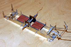
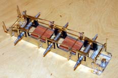
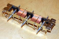
I then glued the rear set of hornblock assemblies in place. Using the axle jigs I was able to use the outside frame parts (not shown) to ensure that the spacing between the axles was correct. Once again the engineer's square was used to make sure of the alignment. After these had cured the front set was done in exactly the same way - making sure the trimmed section of the hornguide was in correctly. After all the glue had hardened off a further quantity was mixed up and run as a fillet around all the hornguides, making sure the hole for the levelling screw isn't obstructed. And that was pretty much it...
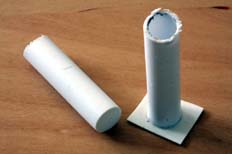
I'd had a suspicion for a while that something was hiding under the front of the tender chassis. Eventually a couple of photos confirmed that there was, indeed, a vacuum reservoir under there. At this point I was working purely from photos and in the process didn't get this area quite correct. When I got hold of the GA I finally managed to work out what was going on under there and decided to replicate it in styrene - mainly because the vacuum reservoirs bridge the tracks I'd cut in the copperclad for the busbars. So it was out with a length of 9.5mm dia Plastruct tubing and a couple of bits of 20/1000" and 60/1000" plasticard.
The vacuum reservoirs were started by roughly cutting off two lengths, both somewhat longer than required. One end of each was trimmed off smooth and square before scrap 20/1000" plasticard was used to blank off that end. Once the Plasticweld had been applied - both inside and out - the parts were left overnight on their ends to harden off.
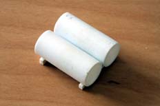
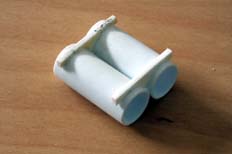
The scrap 20/1000" plasticard was then trimmed off to the outside edge of the tube to give me two open ended cylinders which were then cut off to length. The 60/1000" plasticard is then bought to bear. Two identical cradles are cut from this plasticard. I decided to aim for a 20/1000" (0.5mm) clearance between the reservoirs to provide somewhere for the straps to terminate. I hasten to add that we're back in the 'reason and supposition' department with the strap arrangements; it could quite easily be one strap around both reservoirs. Unfortunately this is a detail not obvious on the GA as it doesn't include a front or rear view!
You'll also note that, at this stage, the cradle is somewhat more sturdy than it really needs to be. Once the solvent has evaporated off it can be trimmed to a better shape.
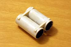
Next job is to fill the reservoirs with lead shot. I know there are various scare stories about the use of liquid lead or similar small shot expanding over time and splitting their container. I must admit I've never had such a problem, but I don't use PVA; I use superglue. The container is part-filled, then liquid 'runny' superglue dribbled on top with that process repeated until the container is full. In the case of our reservoirs I did each one in two stages. After the last superglue is dribbled on top any excess can be wicked away with tissue before it's all left to cure. After the lead fill has cured off the cradle can be trimmed down; I rubbed it down until was flat at the bottom using a mixture of files and emery paper.
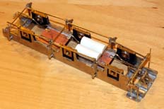
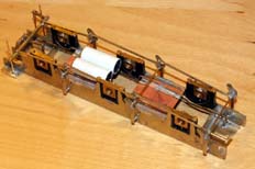
The amount of detail under the frame is determined by two things on my model. Firstly what's credible and sensible to fit because it can be seen; and secondly what adds useful functionality or features to the model. This next stage is good from both perspectives - the steam heat and vacuum pipes can be seen on the underframe and in this model they can act as bus-bars for the pickups.
As you can see they've been carefully bent to keep them clear of the hornblocks and guides before soldering to the copper-clad frame spacers. The bus-bars are made from brass rod; 1.2mm for the steam heat line and 1.6mm for the vacuum brake. To be honest it would have been easier to use copper rod, but I didn't have any of a suitable size to use. And I know these sizes seem to be the wrong way round (usually the brake pipe is smaller than the steam heat line) but these are taken from the dimensions on the GA.
One of the less useful parts, though still noticeable, is the strengthening straps on the sideframes. These are made from more 1.5mm strip, riveted, cropped to length and soldered in place.
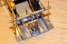
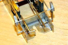
At the front of the frames the bus-bars are trimmed off ready for connectors to be fitted, while at the back they're formed to align with the vacuum and steam heat hoses which will be mounted on the bufferbeam. In the fullness of time further sections of copperclad will be used to support the rods behind the bufferbeam - but I won't be forming them until the hoses themselves have been attached to the bufferbeams.
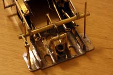
And this is where it starts to get silly. You can see here that I've used short lengths of 1.6mm od brass tube added to the bus-bars in order to make a set of connectors. Similarly I've used sections of the same tube together with double-sided copperclad and short lengths of 0.7mm wire to form the injector water valves. These are isolated from the frames by the copperclad and being epoxied to the hornguides making them useful for a second pair of electrical connectors
So, if the DCC decoder is mounted in the loco then the vacuum brake and steam heat lines can be used to continue the pickups and the injector water valves could be used to connect to the speaker. I think it's worth doing as it saves the effort of trying to hide a four-pole connector and offers a significant enhancement to the detail in this area knowing that they're joined, electrically and prototypically, by four hoses between the loco and tender.
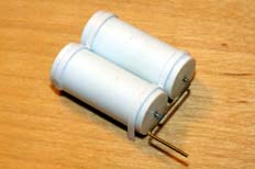
One of the last jobs on the chassis is to finish the vacuum reservoir assembly. This is comprises of three jobs; trim the cradle back to clear the vacuum and steam heat piping; the straps in 10/1000" by 60/1000" microstrip; make up and fit the armature for the piping in 0.7mm brass wire. And yes - the strip used for the straps is a bit thicker than 10/1000"; I only had 15/1000" thick stuff in stock so it'll need a rub down to make it thinner.
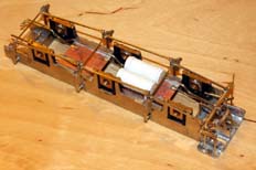
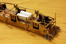
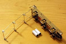
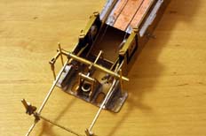
We finish with a few shots showing the overall frame layout, a more detailed shot of the changes made around the front end and a view of it separated ready for painting and/or the installation of the wheels.
Now we move on to assembling the body, before the wheels are fitted.


