Back to Contents
Back to Tips and Tricks
Link to Sitemap
Preparing Slater's 0-gauge wheels for split-axle pick-up
The easy method
Using split axle pick up on trailing wheels of locos (and rolling stock too, I guess) is a lower friction method than using conventional wipers or plungers. It requires a little extra work during construction but the result is a pretty-much maintenance free, low resistance pickup.
I don't think I'd necessarily want to use split axles for driven wheels as I'm not sure I'd like to worry about either insulating gearboxes or having to use a more complicated approach to making the axles.
The approach outlined here is simple, low-tech, consistent and can be considered self-jigging. You'll need a few bits; a piercing saw with No.0 blades, small motor drill such as a Dremel (with 0.5 and 1mm dia bit and a track slitting disc and mandrel), lighter fluid, epoxy resin adhesive (Devcon '2-ton' is the only stuff I'd recommend for this job), cheap masking tape, 26swg copper wire, small hammer and soldering iron, paste flux and a cored electrical solder. A centre-punch and toolmaker's (or other) clamp are also useful. And so off we go...:
Making the axles
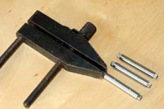
This seems a sensible place to start. In truth the axles only need 'modifying' not 'making'. The first step is to mark two holes through the axle. I normally do these about 8mm in from the back of the wheel but the actual length will depend on the size of the bearings and amount of sideplay in your chassis. The photo shows how the axle can be gripped in a (toolmaker's) clamp on the square end. If it's then put on a stable surface the position of the drill holes can be marked with a centre punch. At this stage it's a good idea to de-grease the axle with lighter fluid in preparation for cutting and gluing.
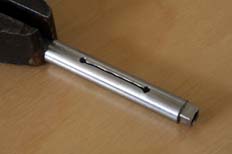
The next step is to drill the holes 1mm and run a slot between them with the saw. It's worth keeping the axle in the clamp until this stage is over, it will reduce the chance of breaking either the drill or saw blade. The holes and slot will need de-burring to reduce the chance of a stray piece of swarf bridging the insulation gap. The finished stage looks like the photo.
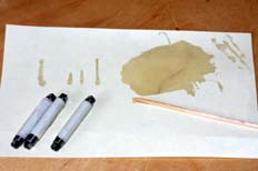
And so to the first lot of gluing. As you can see here I made up a batch of three as part of this exercise. A reasonable quantity of glue needs thoroughly mixing and then can be fed through the slot. I've found that it helps to feed the glue in from one side only and then let it run down through the slot. The Devcon '2-ton' is adequately runny to achieve this. You can see some lines of epoxy on the paper; these are 'witness marks' from where the axles have been standing as the glue runs through. Once the glue has flowed through the joint I wrap the axles in masking tape and press them between my fingers. This may help improve the surface bonding to the steel. The tape must be wrapped tightly round the axle or else the runny adhesive will escape from the joint.
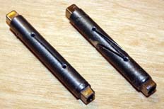
Once the glue has cured off there is one further job. The 1mm holes need re-drilling and slots cutting out to the sides of the axles, followed by de-burring. Once again, holding the axle in a clamp will help save drills and saw blades. As you can see in the picture I cut back at quite a steep angle. This amendment means that the axle is more likely to stay together if the bond should fail. It also offers considerably more bonding surface area and better supports the adhesive. The result is a much stronger axle that's less likely to fail in the first place. The bonding, by the way, is carried out exactly as before. I suppose I should also mention that I tend to do the two side cuts at the same time. Apart from anything else it helps to test that the axle has been properly insulated by the first cut.
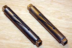
Unwrapping the tape from the axles should reveal an axle looking like the one on the left - covered in glue. Carefull scraping and polishing with fine emery paper will soon provide you with a smooth, shiny axle ready for use.
I suppose I should also mention that if bubbles appear in the epoxy don't be afraid to mix up further quantities of Devcon to fill the voids, before wrapping with tape once more. I have found that this needs doing occasionally.
Modifying the wheels
Here we're using Slater's trailing wheels. The technique I've outlined here uses a rivet and a solder joint, though I suppose two rivets could be used. Or even two solder joints.
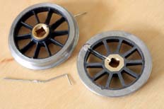
I start by drilling a 0.5mm hole in the boss of the trailing wheel. It's important that it doesn't interfere with the fit of the axle screw in the centre of the wheel, so I always drill this from the front and use a fine centre punch to mark where I want the hole to start. This is the top/left wheel.
I then use the track slitting disc in the drill to run a slot from the hole I've just drilled out to the rim. The bottom/right wheel shows how the slot runs down the back of one of the spokes, and that the rim has been tinned ready for the next stage. You'll probably need to use a goodly quantity of flux paste on the steel and maybe need to polish the area up with some emery paper, a fibreglass brush or similar.
The piece of wire in the bottom/left corner is 26swg copper wire; slightly under 0.5mm dia (you'll see why this is important in a moment!). The right-angle end goes through the 0.5mm hole we drilled in the wheel boss and the kink sets into the groove made in the rim by the slitting disc.
Fit the wire in to the boss and align it down the groove in the back of the wheel. The wheel can be placed upright on a hard, flat surface such as a small anvil or the back of a vice. The exposed wire is then gently tapped down with a hammer; this will cause the copper to 'barrel' out and come into firm contact with the inside of the hole. One riveted connection made.
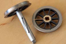
And this is a wheel finished. The end of the copper wire has been soldered into the slot in the back of the rim. After testing with a multi-meter the wheel can be de-greased with lighter fluid and the back of the slot filled with epoxy. Once the epoxy has set the excess wire can be cut off and the back of the wheel rubbed down on emery paper. I then blacken and polish the wheels; alternatively you may want to apply a thin coat of an oil to reduce the chance of tarnishing.
And that's pretty much it. Of course you could use two riveted joints - which I've not tried as I'm not sure how thick the steel tyre on the wheel is. Or two soldered joints, which I have tried and which didn't go exactly to plan though worked in the end.


