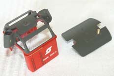
This page is mostly concerned with detailing. The cab is a good place to start with two small and specifically Austrian details to be added.
Back to the fitting of the DCC decoder and re-wheeling.

This page is mostly concerned with detailing. The cab is a good place to start with two small and specifically Austrian details to be added.
The first of these details is the antenna on the cab roof. This could be a small turning if you wished - mine is made from a small section of brass tube soldered onto a thick brass wire. The second is to extend the cab handrails over the access doors. There is no need to make this a subtle addition - ÖBB didn't! The joins in the sections are very obvious in photographs.
The final job is to add a new set of windscreen wipers. using etched ones means they can be accurately positioned against the glazing. And no, I hadn't done that at the time of the photograph...
As you can see I did eventually get round to fiddling with the cab further. With just the windscreen wipers left to do (or so I intended), I had another look at the cab. It soon became clear that the part lines, which were particularly heavy around the cab windows, would cause the odd problem-ette when it came to weathering the model. So I carefully scraped them down with a fresh, curved scalpel blade where they were visible below the handrail. Above the handrail, around the cab windows they required the attention of a needle file. In both cases the areas were then rubbed down with a little 400 grit emery paper. The original Roco windscreen wipers were cut off flush with the surface, leaving the mounting pin in the cab moulding. This could then be drilled through 0.5mm to provide a mounting hole for the Weinert replacements.
I found that Humbrol 174 'Satin Signal Red' was a good match for Roco's red paint. Unfortunately the clour density isn't particularly good, so three thin coats were required. Thankfully it dries fairly smooth if you're carefull how you use it. The dark grey is an elderly tin of Humbrol HR149 'RAL7022 Umbragrau' which is a slightly darker shade than that used by Roco. I must confess I didn't bother matching it any more accurately, deciding instead to repaint the whole of the cab area. To retain the electrifcation flashes on the exhaust cowls they weren't painted. This was a useful opportunity to put some of the grey paint around the inside of the window frames which makes the cab sides seem thinner. Similarly it allowed me to 'crisp up' and correct the shape of the red-grey deliniation.
It's now windscreen wipers time. The Weinert ones are a little bit large for this loco, so needed carefull trimming before assembly. I typically cut frets using a curved scalpel blade, with an old CD box used as backing. Rocking the blade across the locating tag will cleanly seperate fine parts without firing them across the room. I soldered them for strength; a quick touch with an almost-dry iron is all that's required. The picture above shows how I bent the fret around to assemble and blacken them soldered to wire handles. It makes life a lot easier!
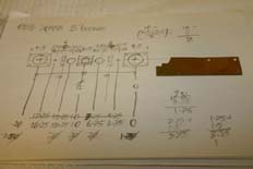
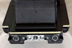
There are some details to be added around the buffer beam. Some of these details represent the differnce between different prototype builders and batches - the two large lightening holes in the bufferbeam seem to be specific only to certain MaK built locos, of which 2048 003 is one.
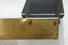
The first picture shows my dimensioned sketch for the bufferbeam details. The dimensions were then transfered onto a piece of scrap 20/1000" (0.5mm) thick brass sheet. The pilot holes were drilled 0.5mm and the buffer holes were drilled to take the old Roco buffers - note that the holes should be different sizes to fit the buffer shanks.
The buffer heads were cut off the bodies and the stubs from the bodies were used to hold the jig in place for pilot drilling. Removing the buffer heads just makes life easier in allowing the drill chuck more clearance.
And after drilling the holes for the brake pipes, coupling socket and the lightening holes the buffer holes are opened out to take a set of Weinert sprung buffers.Of course the usual German-style grabs under the buffers needed adding too, which meant drilling a few more holes to take 0.3mm brass wire.
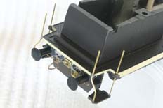
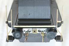
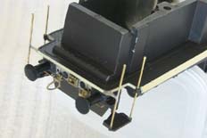
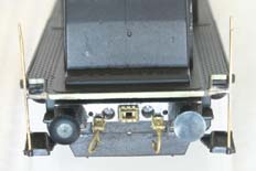
The other main detail of interest is the grab rails and stanchions around the bufferbeams and shunter's steps. On the original Roco model they're made from a flexible plastic and mount onto the underside of the footplate on large lugs. These are both very obvious and wholly unprototypical. On my model the original handrails had become distorted and were never going to look any good to my eyes.
The steps are useful, with their brackets to mount behind the bufferbeam and the lugs that fit in the front of the air brake reservoirs are also worth keeping. The rest had to go! I started by removing the lugs moulded into the chassis with a slitting disc in a mini-drill, cleaning up with needle files. Holes were then drilled in the corners of the running plate to take 0.45mm brass wire. The steps were also drilled to take the new wire, as were the mounting lugs I'd decided to keep.
You can see in the photos above that the shapes aren't that easy to conjure up - I had to form them on the model after fixing to the running plate. The steps were then threaded on from underneath and the whole lot trimmed up. The caps on the handrails were made up from blobs of epoxy resin, which was also used to build up the brackets where they attach to the running plate. It's worth noting that the handrails are supposed to be different at each end of the loco - though I can't work out why!
One final modification made was to use the full depth plough plate. The Kadee couplers can be fitted directly to this - the hole you can see drilled in the middle of it aligns with a pin set into the back of the #18 coupler's shaft. The coupler boxes have to be removed from the bogies in order to clear this plate.
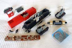
And there we have it; the loco ready for detail painting and final assembly. Clockwise from front left - Circuit board modified for DCC lighting and new motor; Kadee #18 couplers, pinned and fitted to a set of coupling hooks for buffer beam installation; the body components, cab with modified handrails and roof antenna; chassis block with new end details and modified to take the replacement motor and DCC decoder; bogies, re-wheeled and with coupler boxes removed; the new Mashima 1430 motor with the original flywheels and cardan shafts; Zimo MX61/2000 decoder.
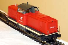
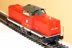
So here we are; other than weathering the loco is now ready for service. Small quantities of various paints (mostly Humbrol with a bit of Revell) have been mixed up to match the existing Roco colours and then used to touch in the areas required. These two photos were re-shot after the page was originally published to the web. The tidied cab, with it's lovely fine windscreen wipers was the last thing to be done to the model.
Thanks to the other work performed it runs well too...