Back to Contents
Back to Railways Page
Link to Sitemap
Back to the first page on the V36...
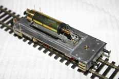
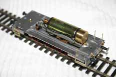
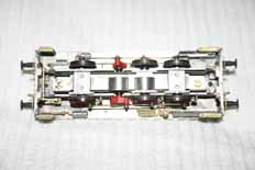
Unsurprisingly this stage took a little bit of time. This is the critical stage of construction if you want a running model. There is inevitably a bit of fitting required to get a cast bodyshell to fit on an etched or machined chassis. Casting is a much less accurate process than either etching or, as in this case, machining. Weinert are much better than other manufacturers in this regard, but even then it's worth thinking about what's going on. I started by fixing the various screws, nuts and bushes into the chassis keeper plate and the running plate. I found I had to trim the nut on the front - it's just visible under the flywheel if you look in the second picture, above. I also deepened the countersink in the middle of the cab floor to give the screw at the rear the chance to bite on a few more threads. I then went for a trial assembly of the various parts to see what else was required. Threading the pickups through the frames is fiddly and holding the three parts (motor and cradle, chassis and footplate assembly) together while trying to do up the two screws (short one under the flywheel; remember?) isn't exactly easy.
First time together it was obvious that the screw holes in the chassis didn't quite line up with the mountings in the footplate. So the parts were carefully disassembled again. I found I had to trim the shims under the motor cradle, and carefully open out the holes in the chassis until I was sure it would line up with the footplate. The second attempt got it together okay; but I then found that the keeperplate wouldn't do up under the front of the footplate. I eventually worked out that there is no clearance in the keeperplate for it to fit round the head of the screw that secures the flywheel end of the motor cradle to the chassis. A novices mistake in the kit tooling that is thankfully very easy to remedy but it would make me wonder if Weinert ever built one of these kits. That is if I didn't know that it was available from the factory ready-built. Hmmmm.
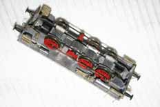
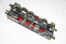
Once it's together it's worth doing a few checks. The obvious one is to be certain that the pickup wipers are where they should be. What do you mean they're not? Oh b..... Make sure the wheels are free to turn and that there's no chance of any shorts which means check those pickups again. Then a test run is worth doing, take care and use the loco at low speed on a good controller. Which means not anything made by a company whose name begins with a 'G'. I use a KPC controller; zero feedback is a good idea when test running coreless motors like the Faulhaber fitted to this loco.
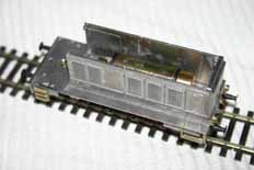
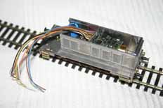
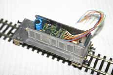
I wanted to see what space was inside the bonnet for DCC stuff so I assembled the bonnet sides and front. There is some detail to go on these parts (and the bonnet top) so that was it for the time being. I screwed the bonnet in place on the footplate and dropped the parts in place. As you can see there's plenty of space for a decoder, the one in the picture is a Zimo MX64. You'll need something good (like a Zimo) to go with the Faulhaber. The capacitor is in there so I can see how much space there is for an on-board power unit; it's a 220pF 25v type; the circuit diagram is in the Zimo instructions. I decided to leave the bonnet as it is in the pictures for the moment as I wanted to do the cab with its new side windows...
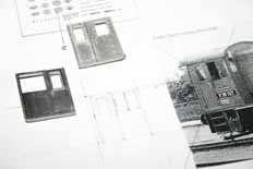
I started off by doing a little sketch using the Weinert cab side parts and good photo as a guide. The picture I worked from is that provided in the instructions. Anyone with basic graphics training will have worked out by the diagonal lines drawn on the cabside exactly what I did. The resulting dimensions put the top and bottom of the cab window cut outs level with the rows of rivets cast in. The front is roughly 1.25mm from the front of the cab, and the rear is roughly 1.25mm in from the cab door. I marked out the shape with a pair of dividers and then cut inside the line with a piercing saw (00 blade), following up with files to get the shape correct. The left hand picture shows one cabside with the new opening, one marked out ready for cutting and the sketch.
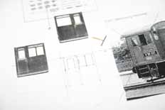
The second picture shows the cabsides with one set of windowframes fitted. The 'T' shape is the window frame unit for the left cabside. The 'frames were made from a piece of scrap fret from an etched brass kit. The strip that was going to form the bottom of the window was tinned on both surfaces with 188° solder and the joint in the 'T' uses the same stuff. It took me a couple of goes to get two good frames out of it; leaving the pieces nice and long helps. They can be trimmed to fit the window after they're made up. The strip that forms the upright in the frame had it's end tinned with 145°. A small rebate was filed in the back of the window cut out along the length of the bottom and where the upright meets the top of the cutout. This allows 70° solder to be run in to hold the brass frame in place. The cabside towards the bottom of the picture clearly shows the blobs of solder remaining at this stage, they were cleaned up once I was certain I had the 'frame in the right place.
Of course there are other ways of making the new window and frame; I considered drawing a green paint line on the glazing material as being a suitable alternative. Styrene frames, or even good quality tape are also useable. The method I chose allows me to use CD box 'crystal' plastic - my preferred glazing material.
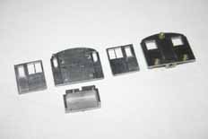
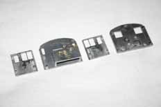
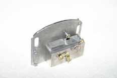
Once I was happy with the cabsides the other cab parts were prepared for assembly. The front gains a hooter on the outside and a handwheel on the inside. The back gets it's three lamps fitted. The lugs on all the applied parts need trimming off after fitting to clear (in particular) the roof which has a thick flange on the inside of the front and rear. The top lamp also needs to lose it's top bolt lug, it too interferes with the fit of the roof. The front and rear cab doors also need closing, the holes for the rear platform safety rails were filled with solder and I then used a curved scalpel to carefully remove any excess solder and the door handles and hinges. The inside surfaces of the cab parts are shown in the middle picture. The file marks from cleaning up the window frames can be seen clearly. In fact after looking at this picture I had another, more successfull, attempt at polishing them out!
The control console has some nice touches. The cast in handbrake wasn't one of them so I replaced it with a seperate piece (Weinert 8682). I drilled through the moulded in handbrake to ensure I located the replacement in the same place and then nibbled off the old one with set of cutters before following up with files. It would have been much easier if I hadn't fitted the other details beforehand...
The controls are going to be much easier to see on my loco with its reconditioned cab rather than a standard loco. So replacing the handbrake was worthwhile. The console won't be fixed in until after painting, that way I can make sure it looks its best if anyone should want to squint through the cab windows.
There should be some a seat and a radiator in there as well; but at this stage I didn't know what they looked like or where they went so I didn't fit anything. It's worth doing a hold-together trial assembly ('dry run') of the cab at this stage. Some of the lugs which guide the parts together will be visible from outside the cab. I trimmed many of them off at 45° to improve the appearance. There are two on the cab front that need more agressive trimming; otherwise they end up in the enlarged cab side windows.
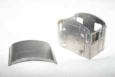
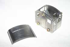
Well, that's the cab done innit? Pretty cool I think you'll agree; the care during preparation of the parts resulted in an assembly that went together properly square and strong. The front and top of the cab side is pretty fragile with the enlarged windows, but once assembled to the other cab parts it's absolutely fine. The holes for the cab door handrails can be drilled now, ready for final assembly after painting. Likewise the cab roof will be left until after painting to be fixed; but it was polished and checked for fit now.
I've decided that it's time for a new page. So there. To join me on the Far Side follow me here.


