Back to Contents
Back to Railways Page
Link to Sitemap
BR38.10
38 1182, 38 2471-1, 38 2929, 38 3860-4
38 1182
is the DR Traditionslok. This loco would appear to be a survivor of one of the earlier batches of P8s, built before the distinctive motion bracket had been adopted as a standard part. I knew that any model of this loco was therefore going to require conversion of the valvegear to this early version. In addition, as I collected more information it became obvious that the footplating in front of the cab was different. Perhaps indicating that this loco originally had one of the enlarged or streamlined cabs. Whatever - by the time it reaches EraIII/IV I knew what the outline of the loco was; and that it would make an interesting modelling project. I don't think I realised quite how 'interesting' it would turn out to be though...
38 2471-1
was one of the handfull of P8s to make it through to EraIV and receive computer numbers. Unusually, most P8s only carried the EDV number plates on the smokebox and tender; '2471 had a full set of Ep IV plates though. This loco remained in pretty much DR condition right to the end. One of the last P8s in service in the DR she survived until June 1972 officially at Bw Roßlau; though she had in fact been seconded to Bw Bautzen.
38 2929
was also a late survivor; allocated to Zittau 'shed until March 1970. One of the strangest outline DR BR38.10s I've ever seen as she was fitted with a Giesel ejector, small DB-style Witte smoke deflectors and had the front feed dome on the boiler replaced with a bolted cover. I've only found photos of the loco in 1970, running with EpIII plates; so that's how I'll model her.
38 3860-4
was the last P8 in operation in the DDR. Like '2929 she was a Zittau loco, withdrawn in October 1972. After this date she was maintained as a Heizlok until final scrapping in April 1975. So it seemed this was an obvious model to make; maybe she'd got to Lokwerkstatt Zittau-Pethau during her time as a Heizlok? This loco also has a Giesel ejector and front dome blanked off, though she retained her Wagner smoke deflectors.
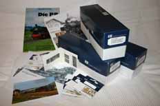
I suppose this is typical starting point for me. Kits, bits and as much information as I can lay my hands on. In many ways this picture shows the difference in philosophy between 'building a kit' and 'making a model'. I had the pictures of a few P8s that would have made suitable models so it was then a case of working out how best to build them. The Weinert kit arrived at the right time and I always think it's easier to convert a kit than to do any serious re-work of an out of the box model. So Weinert it was. The Faulhaber motor and RP25 wheels were a real attraction of course.
The model of 38 1182 looked like being the trickiest to build. So my plan is to build up the model of that loco and then batch-build the other three once I know how the kit goes together. This should save quite a bit of time and stop transferring any problems I may have to all the models. So most of the discussion or description in this piece will cover the building of '1182. Of course any 'problems' are going to be largely self-inflicted with a Weinert kit...
Incidentally, not shown in the picture, but included in the build of '1182, are the Reitz part set for the early valvegear and a Precision Scale air tank. The former set is designed to be fitted to the Fleischmann model of the BR38, which was going to mean some modification somewhere. Thankfully it didn't turn out too tricky at all...
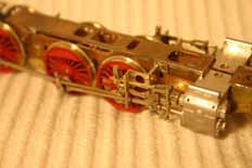
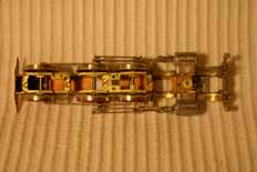
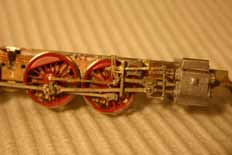
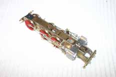
Before I tackled the valvegear the basic chassis had to be built. Well 'built' is probably a slight exaggeration; the spacers were screwed into place and then the parts were soldered together. Easy huh? The wheels (supplied pre-quartered and mounted in their hornblocks) were dropped in minus their springs and then the keeper plates screwed in place. The cylinders were cleaned up and drilled as per the diagram provided in the instructions before being fitted with the screws. Done. Let battle with the valvegear parts commence...
I started by fitting the coupling rods from the Weinert kit to the chassis; this would help me see what the clearances around the slidebars were likely to be. The next job was to determine the correct position of the new Reitz motion bracket. This was designed to fit the Fleischmann loco so I knew it would need modifying. In practise the changes required weren't huge. I cut the front motion bracket support and lug from the Weinert motion bracket casting and then cut the centre out of the Reitz etched part so that the two parts could be soldered together and maintain the original centre distances of the Reitz item. Soldering the two items together with their bottom edges level gave a useable, strong assembly around which the rest of the valvegear could be built. The reversing link is a replacement Weinert part (#9205), which is fitted to the Reitz etched link to the return crank. The Weinert connecting rod, crosshead, slidebar, drop link and combination lever were assembled next. By carefully filing the bottom of the motion bracket where the slidebar fits I was able to make the slidebar parallel and level with the cylinders. The valve spindle is then 'dry' fitted to the cylinders and the top link (from the valve spindle to the reversing link) can then be shortened to fit in the remaining gap. This is assembled back-to-front; the fluting is on the back of the part and used to align a piece of wire soldered in place for reinforcement. At this stage the rear die-block slide on this part was trimmed and crimped together for the lift links to attach to later. It's then a relatively simple job to fit the different parts together - using the Weinert diagrams as a guide. The motion is held in the bracket using the Weinert pins and will remain a friction fit until after the motion assemblies have been blackened and painted.
So there you are - a whole paragraph of incomprehensible gobbledygook to describe what actually turned out to be quite a simple job...
At this stage the chassis is rolling well enough for checking, though the return crank is in the wrong quadrant. In the third picture you can see it leans forward of the axle, which is correct for the locos with the later valvegear: For the early locos it should be behind the axle. I'll have to remember to alter that when the chassis comes apart for the next stage.
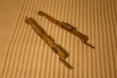
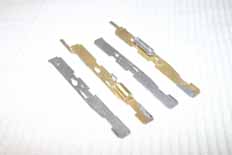
For a loco other than 38 1182 the running plates can probably be modified from the original parts using the Reitz instructions as a guide. For '1182 and its strange cab something more, erm, involved is required. Once again it was Weinert's excellent chequer plate that was used for these assemblies. I'm not going to give a blow-by-blow account of what I did here as the parts I made used the Weinert running plates as templates; to ensure they fitted the rest of the kit! However; the pictures do begin to show how I started to deviate from the instructions at this point. Most Weinert kits seem to start by assembling the basic body and then putting the detailing on. I decided that with brass now involved in the main assembly it would make more sense to assemble the body from a set of detailed sub-assemblies. So, with the running plates made up, the various details from Reitz and Weinert were soldered in place. The brass air tank is the Precision Scale item referred to earlier, suitably refined for use on this model. You can see in both the photos above that there are areas of solder applied to otherwise clean metal; this will allow the running plate assemblies to be low-melt (70°) soldered to the rest of the, whitemetal, body when the time comes. The right hand picture shows the differences between the running plates required by the model, to move the fireman's side feed pump back, provide simple slots for the top of the reversing link and to move the pre-heater to behind the motion bracket.
On the next page you can see how the loco body starts going together.


