Back to Contents
Back to Railways Page
Link to Sitemap
The earlier pages on this loco are back here.
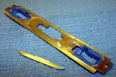
The next job on the chassis is to detail and fix the Frame Runners. This picture shows the Main Frame assembly with one Frame Runner attached. Both have had a 20/1000" (0.5mm) flange soldered along their bottom edges; the material came from a scrap of nickel-silver fret.
The hardest job fixing these parts in place is making sure they're vertical, I got one absolutely perfect, the other much less so! Unless you turn the loco upside down it's not actually all that obvious so I guess it's just a minor irritation. When the fuel tank is fixed on to the chassis it will need to be aligned with the 'good one', otherwise it'll end up off-centre. It would have been a much better idea to get both vertical and align the tank to them both...
You can also see that I've attached the Coupler Pads to the ends of the chassis. There's another layer of brass to go in this area, then the holes will need drilling through and tapping 8BA.
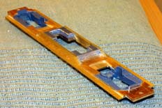
The next job was to start the job of packing weight into the chassis. The aim is to get the all-up weight of this loco to be roughly the same as that of a stock P2k GP9 - which means around a pound (450g-ish). I realised that there are a couple of ways to do this; one method was to use 'liquid lead' or lead shot and stick it in place after the chassis was built. My preferred approach was to use lead sheet and actually build it in as part of the structure.
Lead is a bit of a funny material to work with. For a start there are the obvious health implications of dealing with heavy metals. But for models like this it's very useful, I use lead flashing sheet bought from a builder's merchants. A 1metre length will last quite a while...
I have found that lead works very well when stuck with epoxy resins - Devcon 5-minute has been used to attach the lead in this chassis. It's important that the lead is clean and keyed before attempting to bond it, a brass-bristle spark-plug brush is my chosen weapon. Parallel toolmaker's clamps work very well to hold the parts together as the bond cures because they can apply an even, firm pressure which will reduce the chance of voids in the adhesive.
In the case of the parts in this photo the lead was roughly shaped into a strip with some decent metal working shears. It was then cut roughly to length providing me with four pieces. The pieces were then keyed and bonded to provide me with two roughly-shaped chassis weights. After the adhesive had fully cured (that's around an hour in the case of Devcon 5-minute) the weights can then be shaped with large, rough-cut files. Trimming around the motor cut-out can be done after fixing the weights to the chassis; this is what I did using a number 0 piercing saw blade, very slowly, followed up with files.
Now go and scrub your hands ;-)
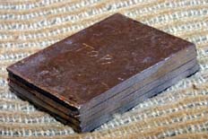
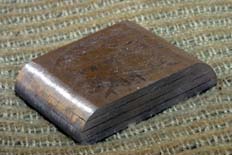
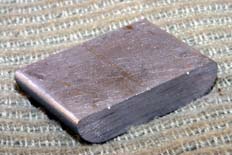
In order to maximise the weight below the frame I decided to make the new fuel tank from solid lead too. There's no reason why you shouldn't use another material; I seriously considered making the shell in styrene and then filling it with lead shot or sheet.
It's not really worth considering use of the original P2k fuel tank. For a start the material used won't easily bond and it's horrible to get a good finish on. Secondly, the CN lightweight GP9s all had smaller tanks - 1000 gallons (Imperial) compared to the 1600 gallon (US) version modelled by Proto. It was just going to be easier making a new one, rather than try and cut-down and clean-up the old one.
The process for making up the tank is much the same as that for the chassis weights referred to earlier. I found that four thicknesses of the lead flashing came to roughly the same depth as the original P2k fuel tank. So I cut out four blanks, keyed them and bonded them together using toolmakers clamps to hold the parts together. After the adhesive had fully cured the blank was then trued up to the overall dimensions with a large file - this is the subject of the first photo.
The second and third photos show the fuel tank after it had been shaped. The section is the same as that for the P2k tank, so I used it as a template. Most of the shaping was done with files, roughing out with a 12" coarse file and working down to needle files. I then used 200grit wet and dry (used wet) to smooth the surfaces, following up with 400grit (again used wet) to leave a good finish for painting.
The last job was to put a couple of marks on the top surface of the tank using a set of dividers; these will help with aligning the tank with the frame when the time comes to fix it in place.
Now, wash your hands again...
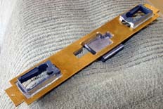
And here it is, fixed in place. You can see how the top of the fuel tank forms the base of the well in which the motor fits. As you'd expect, the bond has been made with Devcon 5-minute; weights were used to hold the parts in alignment as the adhesive cured. It's worth taking care that the fuel tank is stuck at the right end of the underframe; it should be towards the back, nearest to the cab. I only mention this as I managed to glue up the wrong end; thankfully I realised my mistake before the parts were joined...
The glue will cure in around five minutes, becoming fully hard over the next hour or so. Once it is fully hard it's much harder and stronger than the lead of the fuel tank. So I tested the waste glue I had mixed up until it reached a firm jelly-like consistency that was no longer sticky. This took around half an hour. At this point the excess adhesive was trimmed from the fuel tank and frame, but not inside the motor well; I thought the fillet formed might be a good idea to gain some useful extra strength in this area.
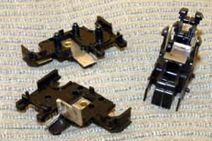
At this point my attention turned to the trucks. They'd already been disassembled for cleaning, re-lubricating and re-wheeling. There are a couple of little jobs required to make them both look and work better. Firstly, I trimmed the top pick-up tab to the same height as the fixing clips. The metal was then tinned with multicore solder. Similarly, for the chassis return I soldered a piece of tinned copper wire to the mounting pad. The location of this wire isn't exactly critical, just as long as it doesn't interfere with the bogie rotation. Soldering this extra terminal on to the trucks is necessary because the glued, composite material construction of the chassis means there's no return path. Modifying the trucks in this fashion allows the pickups to be hard-wired to the decoder, guaranteeing a good electrical path. In terms of improving the appearance of the trucks I painted all the visible bright metal with two thin coats of Humbrol Matt Black. The paint needs to be kept clear of the slots that take the wheel bearings in order that the pickups still work.
When the trucks are re-assembled the gear spindles are lubricated with a sticky grease from Woodland Scenics. The wheels are also replaced with scale 40" versions. These are available from Jay-Bee and North West Short Lines. Or you can do what I did and use a set left over from replacing the wheelsets in a P2k loco that had cracked axle gears. The wheelsets were disassembled and the old P2k wheels used with the original Athearn gears and bearings.
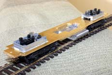
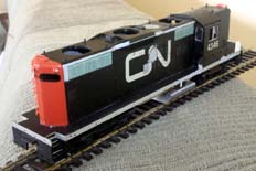
Once the trucks had been modified and re-assembled I trial fitted them to the chassis. The picture shows them installed with their new wheels. Believe it or not that's pretty much it for the structural work on the chassis. There's still some detail and a lot of weight to be added but it's starting to look promising. At this stage I popped the body back on to make sure it all looked right. I think it's beginning to capture the slightly ungainly look of the prototype quite nicely.
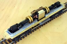
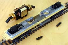
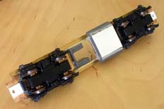
Some more lead has been added on top of the Main Frame. This was made from three layers of flashing bonded with epoxy, which was then cut and filed to clear the cut-outs in the chassis and with two flywheel wells. You'll also note that a shallow channel has been filed in the top to clear the prop shafts.
I've also started the detailing and tweakery. At this stage this includes the tank brackets which come from Details West. You can also see that I've added a 20/1000" (0.5mm) layer of plasticard to the bottom of the tank with epoxy to get it to the desired final thickness; this has been blended into the existing tank shape with a little Milliput. You can also see that the coupler mounting pads have had a layer of plasticard glued on, this has got the couplers to the correct height according to the Kadee height gauge. And if you look really hard you can see that the coupler screw holes have now been tapped through 8BA for the boxes.


